How the simulator works
Basic logic flow
SystemLab|Design utilizes a block-based simulator to model the performance of virtual systems. Before calculating the output signals for a specific functional block, any upstream blocks that are connected to this functional block (through its input ports) must first be calculated, and so on, all the way to the source transmitters (which do not require input port(s) to perform their calculations).
As the connection layout for a system design is not known prior to starting a simulation, the simulator algorithm (which is managed by the calculation_orchestrator method) uses a query-based methodology (while True loop) to ensure that all connected functional blocks are calculated in the correct sequence.
To achieve this, all functional blocks are equipped with an fb_calculation_status flag that notifies the orchestrator when its “Ready” for calculation (this is triggered when all input ports for the fb have received valid signal data from upstream sources).
After completing a calculation, the functional block will update its status to “Calculation complete”. Once the entire list of functional blocks for a design has reached the “Calculation complete” stage, the simulation is considered complete.
For further details on the simulator algorithm model, see Main simulation algorithm.
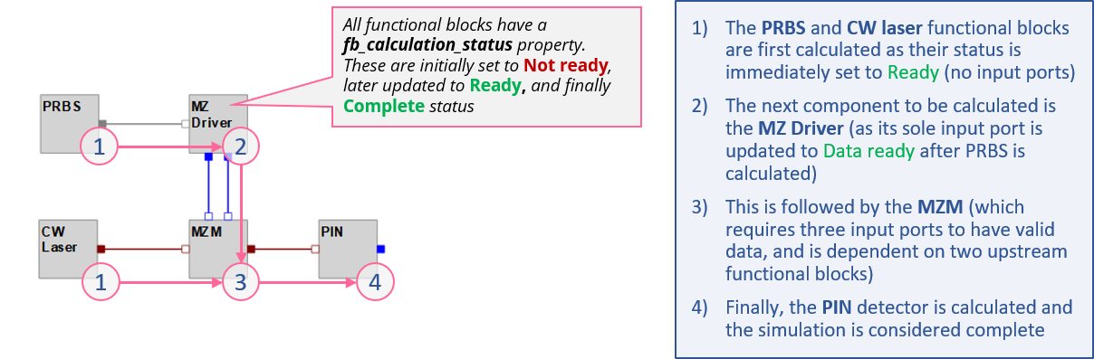
Fig 1: Example calculation flow for a design project
Interpreting the simulator status panel
During the simulation, status messages are sent to the Simulation status dialog. Status messages are received from the Main simulation loop (providing information on the status of each functional block in the simulation and the current iteration/feedback segment being run) and the fb_scripts themselves. The latter messages are important as they capture any data or issues/errors that may have occured while running the script module for any functional block.
An example of a typical stream of status messages is shown in Fig 2. Explanations are included on how to interpret the various message blocks.
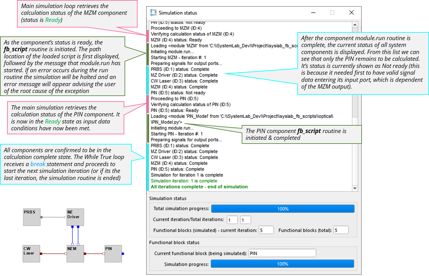
Fig 2: Simulation status dialog (example output)
Error message handling during a simulation (examples)
Example 1: Incorrect script name
In this example, the script for the MZ (Mach Zehnder) Driver was incorrectly entered (“MZ_Driver_PIN_1” vs “MZ_Driver_PIN”). After attempting to find the module in the main scripts library and both project-defined paths, a ModuleNotFoundError exception was raised and a message issued advising the user that no module named MZ_Driver_PIN_1 exists.
The same type of error will be raised if a project file path is incorrectly entered or if the scripts_path_list (linked to the functional block library) does not contain the path for the specified module.
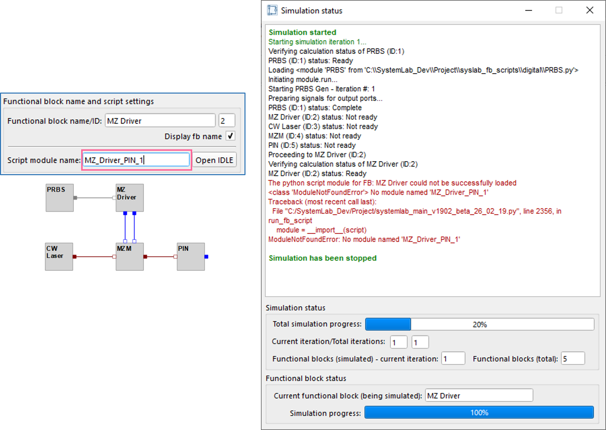
Fig 3: Example error message for “module not found”
Example 2: Parameter field data not entered correctly
In this example, the parameter for the Peak-to-peak amplitude of the MZ (Mach Zehnder) Driver was left blank. When attempting to read this parameter, a ValueError exception was raised within the fb_script routine (expecting to see a float number but instead it read a string/blank field).
When an exception is raised at any point in the fb script module, the simulation will be halted and a detailed error message will be posted to the Simulation status panel. This approach ensures that information on a problem (including the line number in the script), and the affected functional block location, are quickly presented to the user.
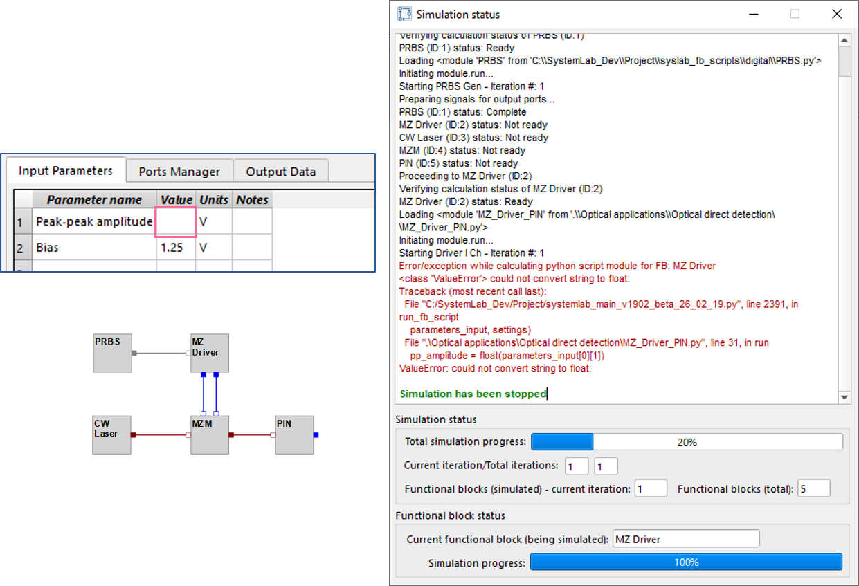
Fig 4: Example error message for a “value error” (in this case the input parameters list)
Questions & Answers
If a functional block/component is not ready when queried by the simulation routine what happens next?
Frequently, especially in larger, more complex designs, downstream functional blocks will remain in the “Not ready” state over several repetitions of the while True loop. To plan for this, each functional block has been equipped with a status counter that is set by default to 10. Each time the main simulation loop retrieves the status for a functional block, the counter increments by 1 if its status is still in the “Not ready” state. If the counter limit is exceeded, the status of the functional block will be changed to “Unable to complete calculation” and will be ignored by the main simulation loop for the remainder of the while True loop. This is important as some functional blocks may never be ready for calculation (for example if one of their input ports has not been connected to an upstream source) and will result in infinite loop conditions!
Tip
You can change the max allowed calculation attempts setting in the Project Properties/Advance settings tab
Is it OK if I don’t connect all my components in the design? Will the simulator still run?
Yes, the simulation routine will still run to completion but will advise the user that it was unable to complete the calculations for some of the functional blocks in the design layout. Designs are frequently works in progress (some sections may be incomplete) and should not limit the ability to perform the assessment of working sections of a design.